
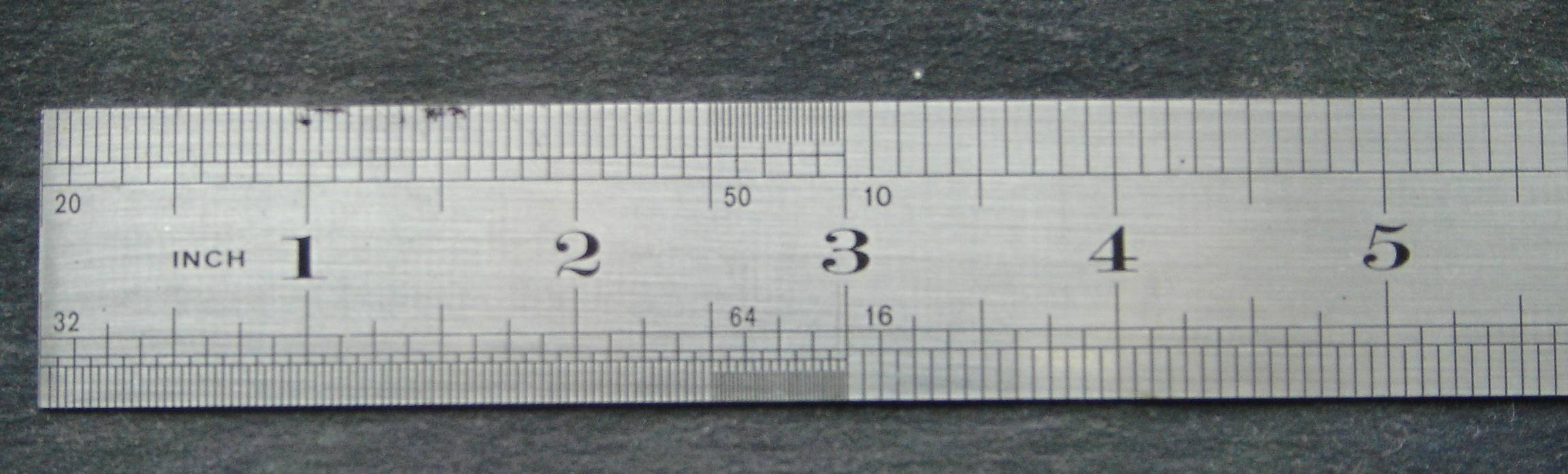
The simplest and most common linear measuring instrument is the steel rule shown in fig.1 steel rules are made of spring steel or stainless steel. Lines, called graduations are inscribed on the face of the rule. Metric rules usually have two sets of line graduations. Steel rules are available in different lengths, the common sizes being 1.50 mm, 300 mm, 500 mm, and 1000 mm.
MICROMETER
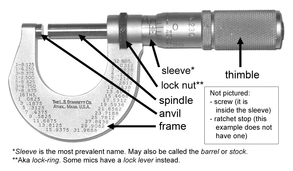
Micrometer or micrometer caliper is one of the most widely used measuring instruments. Micrometer operates on the principle that an accurate screw will advance the spindle a precise amount for each revolution. It consists of a fixed anvil and a movable spindle. The graduated thimble rotates with the spindle and travels along a graduated sleeve fixed to the frame. The graduations conform to the pitch of the micrometer screw. To control the pressure between the anvil, the spindle, and the workpiece being measured, it is equipped with a ratchet or a friction device. Many micrometers are provided with a spindle lock.
Rotating the lock nut in one direction locks the spindle from turning. Micrometer calipers are available with a variety of specially shaped anvils and spindles. The metric micrometer has a spindle screw thread with a pitch of 0.5 mm. with one complete revolution of the screw, the contact face at the end of the spindle either moves away iron or toward the face of the anvil exactly 0.5 mm. The upper set of graduation on the sleeve represents whole millimeters and the lowers set divides each millimeter into two equal parts or 0.5mm, The beveled edge of the thimble is graduated into 50 parts, each graduation representing l/50 of 0.5mm or 0.01 mm. The micrometer reading is established by adding the following three values.
 |
| Fig 2 |
(i) The number of main scale divisions to the left of the 0 on the vernier scale A.
(ii) The line number B on the vernier scale, which is aligned with a line on the beam (main scale)
Vernier caliper reading = A x Length of 1 main scale division + B x least count
 |
| Fig 3. |
VERNIER HEIGHT GAUGE
The vernier height gauge is widely used in layout work and for height measurement up to an accuracy of 0.02mm. It is generally used on a surface plate. The three main parts of the height gauge are the base, the column, and the slide arm. The main scale is on the column and the vernier scale is attached to the slide arm. A flat scriber is secured to the slide arm for layout work as shown in fig 4
 |
| Fig 4. |
BEVEL PROTRACTOR
The bevel protractor shown in fig.5 is used for measurement jor layout of angles. The protractor has a head with a revolving turret graduated to 900 degrees on each side of zero. A vernier is provided to measure the angle accurately. The head is adjustable along a tempered blade
 |
| Fig 5. |


No comments:
Post a Comment
If you have any doubts, please let me know